Friday 27 February 2015

rear Brembo calipers rebuilt

All new seals fitted, slider pins regreased, new caliper springs re-fitted. Fresh coat of paint.


Test fitted to rear uprights and all looks good.

exhaust manifolds welded up

exhaust manifolds were TIG welded up earlier this week, and I'm glad to report they fit the cylinder heads perfectly.

couple of pictures:


View of the collector internals. BMW have done a great job to ensure the primaries meet smoothly and eliminate turbulence. In their case this was to ensure an even distribution of flow into the catalyst for emissions optimisation, but for me it is great to maximise high-rpm power.


The manifolds will eventually get a ceramic coating once the remainder of the exhaust system is complete and welded.


Friday 20 February 2015

more exhaust manifold progress


Now all the the required bends and flanges are here I have been able to really crack on with the exhaust manifolds. 

Started with measuring up the port exits and bolt spacings on the head:

Turned this into a CAD model and printed accurately to scale.


Rather aptly I used the old scrap F355 custom sump pan as the basis for my welding jig. It was easy to machine, I know it is totally flat, and it will act as a nice heat sink when welding. I will just have to be wary of the bore spacing growing during welding due to the thermal expansion of the base plate. Easily rectified by allowing the jig to cool completely between each welding op. = lots of cups of tea and biscuit breaks! ;)


Sectioned each bend shown in the previous post.


Bolted to head with flange to assess the initial leg length and clearances to the surroundings.


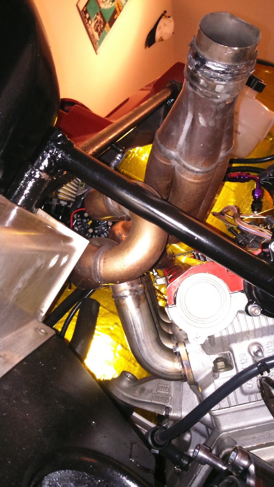
The finished jig, and all the manifold parts rested in position. So the finished manifolds should look something like this:


Final welding I hope will be complete within the next couple of weeks.

Tuesday 10 February 2015

exhaust manifold bends


No major progress over the past couple of days, just minor bits and bobs like plumbing in the clutch and routing more of the coolant and breather hoses.

This afternoon however the remaining bends for my header systems arrived. These are tight radius (only just over 1D) 1.625" stainless pipe. These will be cut in half to create a tight radius 90 which will form the port exits.

Onto these will be welded the E90 M3 4-into-1 manifolds that I showed earlier. These are perfect for the F355 engine in terms of diameter and the fact that BMW did a fantastic job of making all runners equal length, the flow in the collector (has a flow straightener - I will try and get a pic later), and keeping the assembly nice and lightweight. I don't anticipate any power loss through my header system, if anything I might gain a bit as I have more space to play with than on the Ferrari, and obviously I'm not going to be running any catalysts.


On the back of the headers will either go twin carbon cans (re-packable) with twin exits, or possibly both banks coming into one large central can, with a single centre exit tailpipe. I've not quite decided yet.


Wednesday 4 February 2015

wheel speed sensors

The Pectel SQ6 has digital input channels for days, way more capability that I will need for trackdays. There are better ECUs out there nowadays but at the time of it's release the SQ6 was positioned right at the top end of the market for professional Motorsport ECUs. 

www.cosworth.com/media/199295/29e-071516.pdf 
http://www.apexspeedtech.com/products-we-love-what-we-like-about-the-pectel-ecus-part-1-hardware
(if anyone's interested!)

I have some previous experience running them in 6 - 12hour Sports Prototype endurance races from 2006 through 2009 and I don't remember us ever having any issues with them. So safe to say pretty robust.

In order to use up some of the digital inputs I decided to run a twin wheel speed sensor setup on the gearbox. This has a number of small advantages over the stock Lotus S1 set-up where there is a single sensor on the nearside rear upright.
  • The S1 setup will read different between going left-right on long sweeping corners due to that tyre covering a greater/lesser distance.
  • Sensor out on the upright is vulnerable to damage from stones/gravel especially on trackcar.
  • Sensor gap is vulnerable to blocking from rubber/grass/gravel especially on a trackcar.
  • Sensor/bracket and cable all add to unsprung weight on that corner.
With my twin setup I can get the ECU to average the speeds from the two inputs and display on the Pi Omega digital dash. Even though I don't have as many pulses-per-revolution (6 per side) by running a constant average calculation at high frequency I should be able to get a good refresh rate on the dash.

My setup is also far less vulnerable to damage being on the top of the gearbox and even with two sensors is lighter than the Lotus S1 setup.


A good tip for setting up these sensors is to get some thin card and fold to the desired thickness (check with calipers before hand - in my case 1.00mm) insert between sensor and trigger and then clamp up tight in position. I elected to run off the back of the M10 fasteners for the inner CV joint. This is nice and simple and just requires running bolts that are 6-7mm longer than strictly necessary.


Completed sensor in position above drive flange with Torque Seal applied to easily check in future that bolts haven't moved.


Sensors in position either side of rear diff.

Sunday 1 February 2015

Fuel tank plans

Spent some time this morning sorting out plans for the fabrication of my custom aluminium fuel tank.

Using the original steel tank (which I sectioned at the same time as the chassis) and some cardboard I created a template that the fabricators should be able to use as a jig. 


In parallel to this I knocked up an accurate Pro-E model to check the likely tank volume. It came out at 34.5 litres, This includes allowances made for wall thicknesses but not baffles. That number also does not include any additional fuel volume inside lines and inside the filler neck itself. (The pump will be external to the tank which saves on internal volume also.)

All being considered I think 34 litres+/- 1.0 litre is realistic. 

This should be ok for the mainly short track sessions and possible time attack use that I have planned for the car. I will have to wait and see what the maximum road range will be when pootling along in 6th (6th is geared quite long so it might be reasonable..)

Quick pro-E model. The spigots are:
  • Fuel fill.
  • Vent.
  • Return.
  • One to represent level sender wiring.


.